
ASSEMBLY INSTRUCTIONS
STRAIGHT TERMINAL ASSEMBLY INSTRUCTIONS

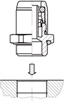
The seal of the stud coupling is specified by what is laid down in ISO standard 6149-80 andDIN standard 3852. To obtain the correct assembly on all terminal fittings it is essential toadhere to the tightening torques shown in the following table.:
| THREAD | TIGHTENINGTORQUE (Nm) ± 10 |
|---|---|
| M 10 X 1 | 22 |
| M 12 X 1,5 | 24 |
| M 14 X 1,5 | 30 |
| M 16 X 1,5 | 35 |
| M 18 X 1,5 | 36 |
| M 22 X 1,5 | 40 |
| M 26 X 1,5 | 45 |

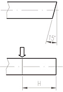
The tubing must be cut at right angles with a maximum tolerance of 15°. Correct assembly isperformed only when the tubing inserted touches the end of the tube seat. To be absolutelycertain that this is the case it is advisable to mark the depth of the tubing coupling (distance H).
| ØPIPE | DEPTH OF COUPLING (H) |
|---|---|
| 6 X 4 | 19,8 |
| 8 X 6 | 20,5 |
| 10 X 7 | 24 |
| 10 X 7,5 | 24 |
| 10 X 8 | 24 |
| 12 X 9 | 25 |
| 15 X 12 | 27 |
| 16 X 12 | 27 |
| 18 X 14 | 27 |

| ØPIPE | FITTING FORCE (H) |
|---|---|
| 6 | 60 |
| 8 | 80 |
| 10 | 82 |
| 12 | 95 |
| 15 | 100 |
| 16 | 100 |
| 18 | 100 |
SWIVEL FITTINGS ASSEMBLY INSTRUCTIONS

Screw the swivel coupling into the thread ensuring correct torque (overtightening can cause damage to both the fitting and the component).
Then fit the component by means of push and twist.
IMPORTANT:
Check the component is coupled properly.
Pull the component to ensure this is the case.
